
Turbo Basics
Notice: Undefined variable: banner in /home/alan92rttt/public_html/rbs_3sgto.php on line 17

Typical setups / diagrams / pictures
How the Turbo / Intercooler stuff works
|
The drawing below (from the Garrett pages) shows the typical Turbo / Intercooler live-circle. Please note that there are no fuel parts necessary to understand the prinziple. |
 |
| So, how does the thing work ??
Why do we need an Intercooler?? Each engine has an optimal temperature operating range. As our different ambients can vary sooo much, the engine computers also measure barmoetric pressure, air temperature and amount of air the engine sucks in. With this the optimal amout if air/fuel ratio for the current ambient is determined and the engine runs in its paramters. Fact: The more heat the engine is getting the less power is produced. For design purposes it is also desired to minimize the variable "intake temperature" as much as possible. But we learned that compressing the air produces heat ! And the more the air is compressed the more heat is produced. Therefore somebody had the idea to cool down the compressed air ... the Intercooler was born. With this element the air is cooled down to acceptable temperatures and allows us freaks to increase the boost without the danger to loose the needed horses. Of course, cooling the engine always helps to keep it longer alive. What is a wastegate ?? Its name says all.... a gate that is able to waste something away. Physics tells us that the faster the turbine wheel turns the faster the compressor wheel turns and therefore the more air will be transported. Also the compression increases due to the speed. Of course, this depends on the style of the compressor wheel, housing and whatever as the boost and rpm curve are not linear together. But this will be dicussed sometimes later... The wastegate now is a device that can control the boost by releasing (wasting) some amount of the exhaust gases to the exhaust BEFORE traveling to the Turbine Wheel. Therefore the Compressor Wheels is not driven that fast and boost is reduced. The wastegate is opened by a actuator, driven by air pressure. The actuator is preloaded with a spring and opens the wastegate when the pressure applied exceeds the springs load. Usually the Compressors output will be connected by a vacuum hose to the wastegate-actuator. Therefore the bigger the boost of the compressor the more the wastegate opens and the less boost will be produced. But less boost means closing the wastegate more and therefore more boost will be produced. To get more control for opening and closing the wastegates, the 3000GT/Stealth are having a solenoid valve that, activated by the ECU, releaves some of the boost out of the hose that runs to the wastegate acuators. This circle regulates the boost our car needs to go that fast. This is the basic functionality for getting more boost. |
|
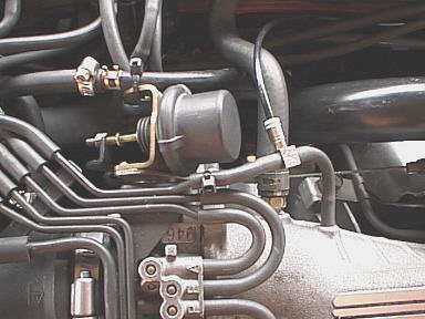
This is the easiest and cheapest modification to a Turbo-driven engine. For only a few $ you can get about 20% more power out of your beast ! This section shows why it works and also the danger of it ! From the previos section, we know how a wastegate acts. Check out the picture below. At the y-pipe from the intercoolers (the black plastic ellbow that goes into the throttle body) a vacuum hose is attached right at the ellbow (marked red). This hose is running to a hose distributor called H-connector. At this point, the pressure is distributed to the front and rear wastegates as well to a stock solenoid valve. This valve helps the stock system to increase boost by releasing some of the pressure in this hose connection into the intake part. This means, if the solenoid valve is open, pressure to the wastegate actuators will be lowered and the wastegates stay closed or even will be activated later. If the solenoid closes the valve the full pressure from the y-pipe goes to the actuators and, if pressure becomes more than the load of the actuators spring, the wastegate opens and therefore less boost will be produced. |
 |
|
Now we know that the stock system controls the wastegates somewhat consevative and the maximum boost is about 8 to 12 psi maximum that can be achieved. But if you look at the drawing there must become something in mind. What will happen if I drop the pressure in the actuator lines compared to the pressure i nthe y-pipe ? You're right, the actuators will be activated later as boost rises. Therefore, if we are able to release about 2 psi of boost, we are having an advantage now of 2 psi and gained that amount of boost ! On our cars, this modification is easy, ..... but dangerous as well : If the vacuum lines for the wastegate would leak and stay at atmospheric level the wastegates would never open and you're car would run like hell around 20-30psi. But this would not last for long as it'll kill your engine for sure... |
|
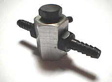
It can be done with the help of a cheap aquarium valve that acts as a Bleeder Valve. In my setup I did 2 years ago, I used a professional bleeder valve with a locking screw. It's very good quality and withstand high temperatures. Also it cannot readjust itselfs... |
 |
|
Here you see how this bleeder valve MUST WORK ! The blue arrow should show the pressure in the line. A part of it is then bleeded to nowhere (or just the ambient) to reduce the overall pressure in the line. Note, with only this kind of bleeder and at this position, the best performance can be achieved. This because the stock solenoid still controls the boost by the solenoid valve. If you do a differnt setup, then you'll always loose low-end power |
 |
|
Where do I place the bleeder valve?
First, check out the modified picture below. Here you can see that the valve is just placed before the stock solenoid valve. This because it's so easy to reach to and can be removed within seconds :) Please note, that you have to locate the hose comming up from the H-connector ! This is the right hose as the ones at the stock solenoid could be exchanged. |
 |
|
Also note the aftermarket boost meter we need! You must have it as the stock unit is inaccurate, too slow and shows not enough on it's scale. A definite MUST for tuning in your new system. |
|
To connect the gauge simply cut the line that comes from the upper part of the intake manifold in the middle and use a T-piece to connect the additional hose that runs to the meter. The hose can then go through the firewall (under the steering column) in to the cabine. Do this before you install the bleeder valve and go for a run to see if your readings are fine and you're not having any vacuum leak. With the stock setting you should see about 6 - 10psi, depending on the year and health of your car. |
 |
|
Now locate the hose that goes into the stock solenoid valve. If you have an additional hose just pull it from the stock piece and plug it to the one side of the bleeder valve. Now use another piece of hose, connect it to the other side of the bleeder valve and plug the other end to the stock solenoid valve. Secure both side of the bleeder valve with small clamp or wire ties. Voilà, that's it. Finally check for any vacuum leak as this is the evil for any failures. |
|
|
How do I adjust the bleeder valve ?
First, close the valve as much as possible and then just open it a little. Drive the car savely and watch the boost meter. On our cars, the most boost will be produced in 3rd gear from 3500rpm till about 5700rpm. Of course it depends on your mods, age and more. S just drive your car in 2nd, hammer it through this band and go into 3rd around 5000rpm. Rpm will drop to about 4000rpms and boost rises very quick. Always keep an eye on the gauge and do not exceed any boost over 15psi. If your car makes less than 14psi open the valve a little bit more and secure the screw. Do this again and again until you're at 14psi peak. Of course close it more if you overboost !! |
As the 1st generation where limited to 8psi these cars will gain a lot ! My european 3000GT TT made 284hp stock and we peaked up to 352hp with just this mod. This was in winter time and after we checked it again in summer time we got about 334hp. After readjusting the valve we where back at around 345 horses. The bleeder valve cannot work like a boost controller. This because it's a passive thing and it cannot toggle the valve to wave-up the boost or to limit it. Therefore it was only a timely mod as I saved the money or just waited until the boost controllers became reachable for my wallet. Read the next section about the boost controller setup. I highly recommend a boost controller against the bleeder valve ! |
Typical boost controller setup in our cars
|
The following drawing shows the turbo-system of the 3000GT/Stealth TwinTurbo cars with a typical boost-controller attached. Of course, my drawing is not complete in all details but contains the parts that are needed to understand how the system works. Remember the described stock solenoid valve ? It releaves some of the boost that goes to the wastegate actuators and therefore keep them closed longer as they would if the the boost at the actuators is the same like in the intake. Also remeber the bleeder valve, with its help we kept the wastegates closed even longer. But all this setups do not allow to control the wastegates optimally. So the best thing is to add an intelligent Boost Controller to your cars turbo system. |
 |
|
As described earlier, less pressure to the wastegate actuators that their springs load keeps the wastegates closed. For this, the boost controllers are using their own valve to reduce the pressure that goes to the actuators. The picture shows the typical setup. The source for the boost pressure is the hose connected to the elbow of the intercooler Y-pipe that combines the two intercoller pipes and goes into the Throttlebody. This hose is now connected directly to the IN port of the solenoid valve of the BC. The OUT port of the box will then be conntected to the front and rear wastegate actuators. Please note, that no bleeder valve nor the stock solenoid valve is needed because the BC does its job perfectly with its own valves. To keep the drawing as realistic as possible, I left the H-connector in place and only capped the one hose that went to the stock solenoid valve. Also the valves input was capped. A big note : Always check for any vaccum leak as this is the evil for all problems and never overboost |
© Copyright 1998 3000GT Web Team. All Rights Reserved.