
Modifications - Gauges


A selection of carefully considered and well placed gauges can make your high performance experience much more enjoyable. You will know the operating condition of your engine at all times and more importantly be able to detect dangerous engine conditions and correct them before permanent damage is done. Gauges should always be mounted in a location where they can be easily viewed without hampering the driver's ability to maintain a view of the road. A-pillar pods are available to accomodate one or two gauges.
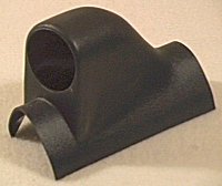 Single Gauge A-pillar
Mount
Single Gauge A-pillar
Mount
Although expensive, consider peak hold and if possible logging capabilites. It is often difficult to safely observe several gauges at a given single point in time, then try to recall later these values and the conditions under which you were operating.
Boost Gauge
Unfortunately the factory boost gauge is not accurate above 7 psi of manifold pressure. It derives boost by through a calculation based on engine RPM and airflow through the MAS. There is no way to make the stock boost gauge accurate. To remedy this, an aftermarket boost gauge must be used. Most people opt to leave the stock boost gauge in place and mount the aftermarket gauge elsewhere, such as on the A-pillar or on the steering column. The stock boost gauge may be replaced with an aftermarket one but it requires removal of the entire dash assembly. There is a wide variety of boost gauges and there really isn't a "best". VDO, SPI, Autometer, and Westach are examples of boost gauge manufacturers. Choose one that reacts quickly, is stable and is accurate.
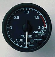 Boost Gauge
EGT
An exhaust gas temperature (EGT) gauge, as the name implies, monitors the temperature of spent exhaust gases. A thermocouple, called the pyrometer, is installed somewhere in the exhaust system. The pyrometer generates a voltage which is calibrated to correspond with temperature. Ideally the pyrometer will be roughly 10 inches from the flame front. This is option not practical however so somewhere in the exhaust manifold (before the turbo) is logical. This is fairly easy to do for the front cylinder bank but less so for the rear. Some people save the extra work required to remove the rear turbo to get at the manifold by installing the pyrometer in the oxygen sensor housing of the rear pre-cat pipe. Note that temperatures at that location will be somewhere between 200° F and 300° F lower than at the manifold. The EGT gauge is an invaluable tool used to monitor and tune the fuel mixture. K type pyrometers are typically standard but it certainly does not hurt to ask. Other styles may not react quickly enough to changes in temperature to be useful. It is not uncommon for gauges to be off by 25 F degrees or so since they are calibrated at specific temperatures. When purchasing from Westach, be sure to specifiy automotive applications or you may end up with a pyrometer calibrated for a snowmobile or an aircraft.
Oxygen Sensor Voltage
A healthy oxygen or O2 sensor generates a voltage between approximately 0 and 1.0 volts. Voltages below 0.45v tend to indicate a lean (oxygen rich) mixture, while voltages above 0.45v incidcate a rich (oxygen starved) mixture. In closed loop operation the ECU uses the O2 sensor voltage to adjust the mixture for optimal fuel economy. The ECU is really only interested in the number of times the voltage exceeds 0.45v. During open loop operation (typically under WOT and acceleration situations) the O2 sensor voltage is ignored by the ECU. O2 sensor voltage is not linear in relation to the mixture. The sensors degrade over time and were notdesigned to be absolute reference devices. Furthermore, O2 sensor voltages can vary from sensor to sensor and over the life of the sensor for a given actual mixture. O2 sensor voltage should never be used as an actual measurement of mixture but rather a general indication of mixture. Very expensive sensors do exist which may be used to measure actual mixtures but their cost is prohibitive for most enthusiasts. The Honda VTEC-R type engines reportedly use a UEGO (Universal Exhaust Gas Oxygen) sensor which apparently has far more linear behavior than typical sensors.
Cyberdyne, Halman and others make reasonably priced gauges. Several locations on the Internet provide schematics for the home builder. A simple DVM can also be used. The TRE MASC includes an O2 sensor voltage display as part of its base functionality.
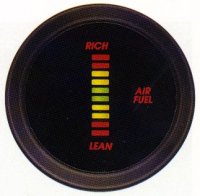 Cyberdyne AFR
Gauge
Cyberdyne AFR
Gauge
Injector Duty Cycle
Injector duty cycle (IDC) is the amount of time the injectors are pulsed to open expressed as a percentage of time. 82% IDC indicates that the injectors are open 82% of the time. Injectors that are open 98% or higher are definitely too small for the application. Most experts recommend no more than 80% constant IDC. For short bursts 90% should be a practical maximum. Halman makes such a gauge. Both the Apex'i SAVC-R boost controller and TRE MASC fuel controller include IDC gauges in addition to their base functionality.
Fuel Pressure
Fuel pressure is a critical and often overlooked factor especially in a forced induction application. Normally aspirated engines always operate under vacuum so fuel pressure is less important than actual fuel flow capacity. In a turbocharged engine under boost the manifold operates in a positive pressure environment. Compressed air is working against the injectors. Higher fuel pressure is required to overcome the boost pressure. Furthermore, boost pressures may vary introducing yet another complication. See the fuel delivery section for more information. Insufficient fuel pressure for a given boost level is a sure way to starve an engine of fuel and possibly destroy it.
Autometer and many others make a wide variety of fuel pressure gauges. Ideally you will not want one that routes fuel into the cabin which means a sensor will be installed somewhere in the fuel line.
 Fuel Pressure Gauge